
Design verification is a critical step in the back-end design process. Ensuring manufacturability before production is key to maximizing yield, which is why compromising on quality isn’t an option. You need a DRC capable of handling the complex rules required by modern foundry processes.
Beyond manufacturability, verification modules also confirm that devices are built to your specific design intent. They validate device inventory, specifications, and interconnects against the reference netlist to ensure everything is properly documented and connected as designed.
Design Workshop Technologies provides a complete suite of verification tools, including DRC, XDRC, and HLVS, to support all these requirements.
Design Rule Check (DRC)
Integrated, Flexible, and Precise Layout Verification
The DW Layout Editor’s Design Rule Check (DRC) offers a powerful, integrated solution for validating physical layouts quickly and accurately. Supporting both single-layer and two-layer rule checks—including width, spacing, inclusion, and overlap—our DRC uses a robust Boolean engine to handle complex all-angle logic combinations.
Customize verification and exception areas effortlessly, and run checks interactively through an intuitive graphical interface or automate them using GPE scripting.
Errors are clearly highlighted with color-coded markers and detailed labels, making it easy to pinpoint issues. Plus, comprehensive graphical error reports can be shared seamlessly with colleagues, vendors, or clients using our Viewer software products, enhancing collaboration and speeding up design reviews.
Advanced Design Rule Check (XDRC)
Unmatched Accuracy and Flexibility for Cutting-Edge Technologies
The XDRC module delivers an industry-leading physical verification tool tailored for the most advanced technology nodes. With unparalleled performance and precision, XDRC excels at handling all-angle geometries, detecting layout errors that other tools may miss.
XDRC can cover the rule sets of all the major foundries, XDRC’s powerful yet easy-to-learn scripting language offers comprehensive commands for every verification need, including width, spacing, overlap, extensions, conditional checks, property evaluations, error filtering, and connectivity rules like antenna checks.
Ideal for electronics, photonics, MEMS, and hybrid designs, XDRC provides a cost-effective and reliable solution for interactive physical verification, helping designers confidently prepare layouts for tape-out and manufacturing.
Design Rule Verification (XDRC)
HLVS: Extraction & Layout vs. Schematic (LVS)
Accurate Network Extraction and Validation for Any Technology
The HLVS module unlocks powerful features like electrical layout extraction and netlist comparison, critical steps in ensuring design accuracy. Fully integrated with the DW Layout Editor and its flexible GPE scripting environment, HLVS can be easily customized to support virtually any process technology or design application.
HLVS includes:
- HLE (Hierarchical Layout Extraction): Automatically generates a netlist from your physical layout, capturing both generic and hierarchical devices along with parameters and parasitics.
- LVS (Layout vs. Schematic): Compares the extracted netlist against a reference to quickly identify mismatches or connectivity issues.
With HLVS, designers gain a robust, efficient toolset for verifying that the physical implementation faithfully reflects the intended schematic, ensuring design integrity from layout to fabrication.
AutoCAD Conversion & GDSII Validation
From General CAD to Fabrication-Ready Layouts
While AutoCAD is a popular format for mechanical design, simulation, and general CAD applications, it’s not ideally suited for mask manufacturing.
Design Workshop Technologies bridges this gap with a Bidirectional AutoCAD Translator that includes built-in GDSII compliance validation. This powerful tool enables designers to seamlessly convert AutoCAD files into manufacturing-ready mask layouts within the DW Layout Editor—ensuring accuracy, efficiency, and compatibility with industry standards.
Data Conversion for Manufacturing (DCM)
Support for GDSII, OASIS, and Advanced EBEAM Formats
The DW Layout Editor comes standard with support for GDSII and OASIS file formats. For advanced manufacturing workflows, the optional DCM module adds compatibility with key EBEAM formats including MEBES, JEOL-01, JEOL-51, and Cambridge SPD.
Fast, reliable data conversion is essential for any CAD system that integrates with multiple tools across the design and fabrication pipeline. The DW Layout Editor ensures smooth interoperability with a wide range of industry-standard formats.
Custom Conversion Services
Need a converter that’s not listed? Contact us to check availability or request support for additional file formats.
PCell Developer Kit
Accelerate Layout Creation with Parametric Cells (PCells)
Design Faster. Customize Instantly. Iterate with Ease.
Save valuable time by automatically generating layout cells with DW Layout Editor’s powerful PCell technology. Whether you’re using built-in library components or defining your own, PCells let you quickly create complex designs through simple parameter inputs.
Just enter your values, via the intuitive interface or a script, and the device layout is generated instantly. Need to make a change? Select the cell, update the parameters in the dialog box, and the layout is redrawn on the spot.
At the core of this flexibility is DW Layout Editor’s GPE scripting engine, which gives you complete control over how PCells are defined and behave. It even detects changes to PCell definitions and ensures all instances are automatically updated.
With PCells and the DW Layout Editor, you get the ideal balance of speed, precision, and customization, making every design faster to build and easier to refine.
Die Serialization
Easily Track and Identify Every Chip with Automated Wafer Serialization
Our Wafer Serialization module streamlines the process of adding unique, printable labels to each chip on your layout—ensuring precise row-column identification across the wafer. With full integration into the user interface and GPE support for seamless automation, it fits effortlessly into your workflow.
Packed with flexible options, you can customize numbering direction, orientation, fonts, and more, giving you complete control over how your chips are marked. Simplify traceability and boost manufacturing efficiency with a serialization solution built for modern design needs.
Photonics Element Library
Streamline Your Path from Design to Fabrication
The Photonics Element Library delivers a complete backend solution for photonic device design. Built specifically for the photonics industry, it takes full advantage of the DW Layout Editor’s powerful features, including all-angle geometry, native GDSII support, and a hierarchical design database.
With a rich collection of parametric optical elements and ready-to-use waveguide components, the library enables fast, accurate transitions from simulation to fabrication-ready layouts, helping you save time, reduce errors, and bring products to market faster.
Document Photonics Element Library (PEL)
Parametric Waveguide Elements for Seamless Photonic Design
Each waveguide element is a parametric cell (PCell) developed by our engineers to meet both photonic design standards and fabrication requirements. Designers can easily use these elements by selecting the desired component, assigning parameter values, and placing it into the layout. This process can also be automated using the GPE. Once placed, the waveguide element is immediately available for viewing or editing in its ready-for-manufacturing form.
Element list
- Linear
- Arc Bend
- Arc S-Bend
- Sine S-Bend
- Cosine S-Bend
- Polynomial
- Elliptic
- Ring
- Polygon
- Linear Taper
- Arc Taper
- Arc S-Bend Taper
- Sine S-Bend Taper
- Cosine S-Bend Taper
- Polynomial S-Bend Taper
- Exponential Taper
- Parabolic Taper
- Circular Lens
- Elliptic Lens
- Parabolic Lens
- Hyperbolic Lens
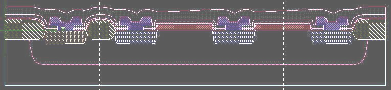
Cross-Section Viewer
Generate Accurate Cross-Section Views for Design Documentation
This module allows you to create precise cross-section views of your design using a GPE script. Each process step like Implant, Diffuse, Grow, Deposit, Etch, and Planarize, is scripted to build the view step by step. Parameters such as thickness, width, depth, slope, and oversize enhance control and accuracy. High-quality visualizations depend on precise input and a strong understanding of process mechanics to ensure realistic and effective results.